This article is about building a bidirectional MAVLink Wi-Fi telemetry module for the Pixhawk flight controller using an ESP8266 module with the MavESP8266 firmware. The newer Pixracer flight controller has a built-in connector for ESP-01 Wi-Fi modules, which can be flashed with the MavESP8266 firmware. This firmware can also be flashed to other ESP8266 based modules and the modules can also be connected to a Pixhawk.
In short these are the necessary steps:
- Flash an ESP8266 based module with the MavESP8266 firmware.
- Connect the module to one of the Pixhawk’s telemetry ports (preferably TELEM1): TX-RX, RX-TX, GND and VCC with 5 V to 3.3 V voltage regulator.
- Configure Pixhawk and telemetry module to use the same baud rate.
- Connect computer to telemetry module’s Wi-Fi network and select UDP connection in Mission Planner (port 14550) or use QGroundControl.
The steps are layed out in detail in the rest of this article and demonstrated with an AI-Thinker ESP-07 Wi-Fi module.
Choosing an ESP module
To prevent confusion, first a note on the naming of ESP(8266) modules. ESP8266 is a Wi-Fi chip manufactured by Espressif Systems. It is used in a variety of Wi-Fi modules, most of them being named ESP-XX (XX representing numerics) and developed by AI-Thinker. These Wi-Fi modules are in turn part of different Wi-Fi boards/modules, but can also be used stand-alone. In this article, if not referring to a particular module, the term ESP module is used to refer to all these ESP8266 enabled modules. The term ESP telemetry module is used for modules that have been flashed with the MavESP8266 firmware.
There are various ESP-XX modules available. Basically all of these modules should work as a Pixhawk telemetry module, as long as they provide access to the following connectors: TX (GPIO1), RX (GPIO3), GPIO0, GPIO2, GND and VCC. Alternatively a NodeMCU development board can be used, which has a serial to USB converter onboard and thus makes flashing the firmware easier. Other ESP8266 based modules like the Adafruit HUZZAH ESP8266 Breakout or the WEMOS D1 mini pro should also work.
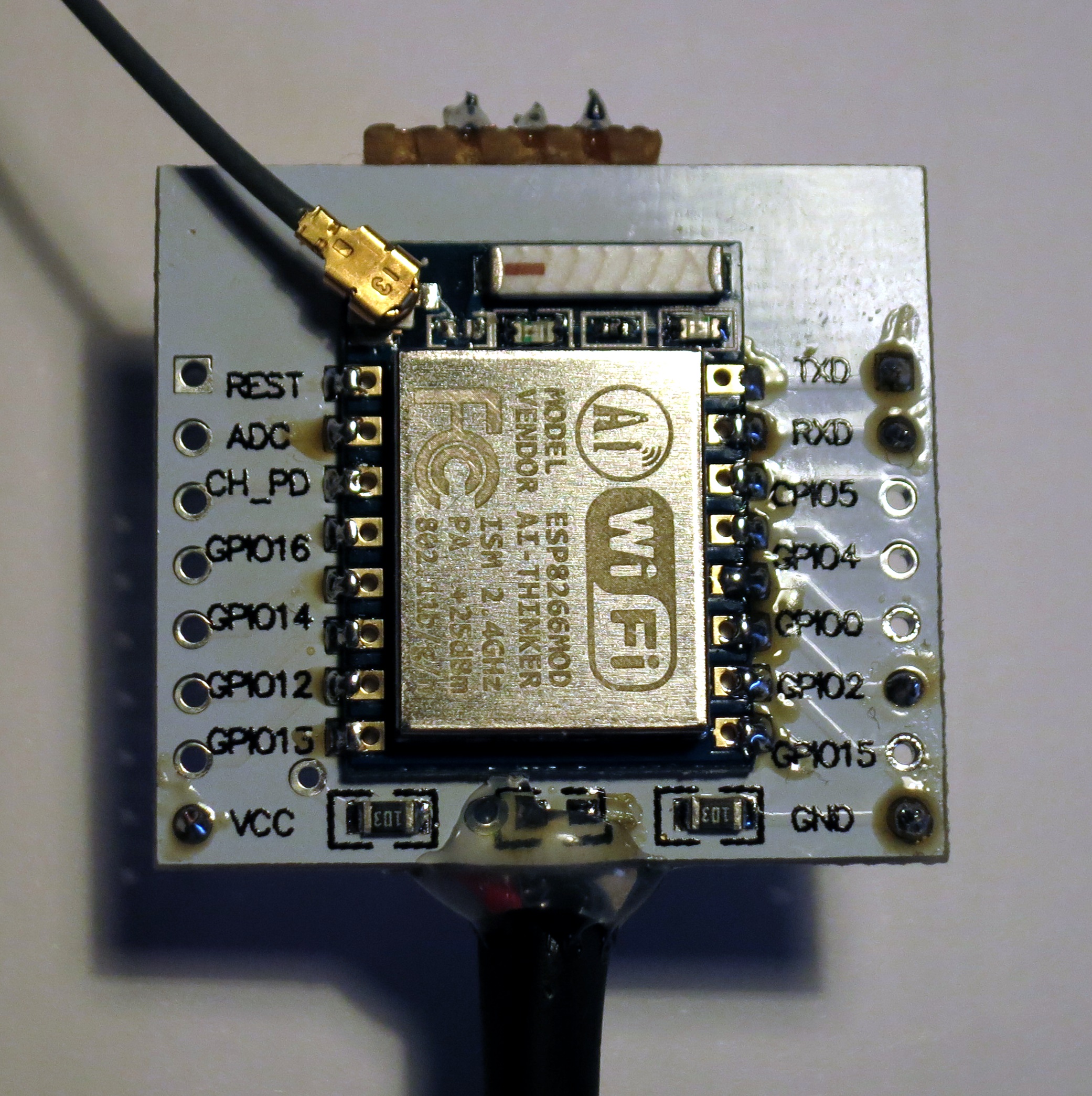
I chose an ESP-07 module, because it has shielding and an U.FL connector for an external antenna. In addition I used a breakout board („adapter plate“), because it makes accessing the contacts easier and it has two 1 kΩ resistors soldered on which pull GPIO15 low and CH_PD high. The picture shows the ESP-07 module soldered to the breakout board:
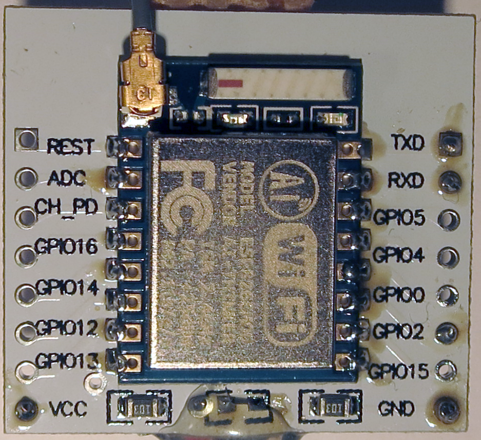 Some of the ESP modules, e.g. the NodeMCU development board, already have GPIO15 and CH_PD correctly wired up. If you are looking for the easiest solution, I suggest to choose a NodeMCU development board. In addition to the built-in serial to USB converter and the pins correctly pulled low or high, it also has a button to set the ESP module to flashing mode and a 5 V to 3.3 V voltage converter on board. It comes at the cost of a slightly bigger size though, and it lacks a connector for an external antenna.
The „Arduino core for ESP8266 WiFi chip“ documentation provides general information about the minimal wiring for UART download mode (firmware flashing) and for normal operation of ESP modules.
Flashing the firmware
You can either build the firmware yourself or use a precompiled binary. I chose the precompiled firmware which is linked on pixhawk.org’s ESP8266 Wi-Fi module setup page (firmware-1.1.0.bin at the time of writing).
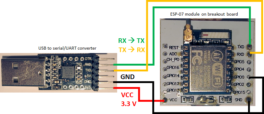
To flash the firmware, the ESP module needs to be connected to a computer. If the module has an USB to serial converter built in, simply connect it over USB. Otherwise you need an USB to serial/UART converter. The wiring for the ESP-07 module sitting on the breakout board to an USB to serial/UART converter looks like this:
Beware that the ESP-XX modules operate on 3.3 V and are not 5 V tolerant on VCC (the GPIOs are 5 V tolerant). GPIO0 needs to be pulled low (i.e. connected to ground) to bring the module into flashing mode.
For UART download mode (i.e. firmware flashing mode) as well as for normal operation of ESP modules GPIO15 needs to be pulled low and CH_PD needs to be pulled high. As mentioned before, these connections are included in the breakout board and are therefor not shown in the picture above. This might be different when using other modules. For example, when flashing (and operating) ESP-01 modules, CH_PD needs to be pulled high externally, whereas GPIO15 is already pulled low on the module. The ESP8266 Wi-Fi module setup page shows the wiring for flashing ESP-01 modules.
On Windows, a very convenient tool for flashing the firmware is the NodeMCU Flasher, which not only works with the NodeMCU development board but also with other ESP modules. To use it follow these steps:
- Start ESP8266Flasher.exe and if necessary go to the Advanced tab and Restore defaults.
- On the Config tab, activate (only) the first line and select your firmware file and 0x00000:

- Connect your ESP module to USB in UART download mode. UART download mode is activated either by manually connecting GPIO0 to ground (see picture above) or by pressing and holding the flash button on your board while applying power (e.g. when using a NodeMCU development board).
- On the Operation tab, select the COM port of the ESP module, press Flash(F) and wait for the operation to finish.
- If flashing does not work or the „Pixracer“ Wi-Fi network does not appear (see below), try to change the SPI Mode on the Advanced tab to QIO and repeat the previous steps. If it still does not work, you might need to build the firmware yourself for your specific module.
After removing the connection from GPIO0 to ground and power cycling the module, you should now be able to find a new Wi-Fi network „Pixracer“ and to connect to it (password „pixracer“).
Instead of the NodeMCU Flasher, esptool.py can be used to flash the pre-built firmware. It works on Windows, Linux and OS X.
Connecting the ESP telemetry module to a Pixhawk
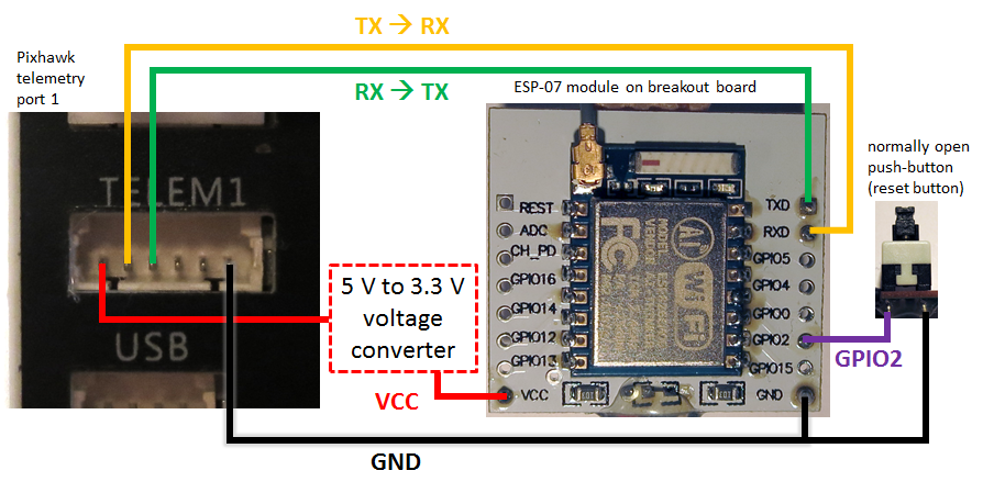
The ESP telemetry module needs to be connected to 4 pins of one of the Pixhawk’s telemetry ports (VCC, TX, RX, GND):
Both devices use 3.3 V for serial communication, so TX and RX lines can be directly connected, as well as GND. The Pixhawk’s telemetry ports provide 5 V VCC, whereas the ESP-XX modules operate on 3.3 V, so the VCC voltage needs to be converted. If using a board with a built-in voltage converter (like the NodeMCU development board), simply use its 5 V input connector. If not, the easiest solution for connecting VCC is to use a DC-DC step down module – e.g. with an AMS1117 3.3V chip. Just choose one which can deliver sufficient current.
Information about current consumption of the ESP8266 chip / ESP modules varies:
| Condition (source of information linked) | Current |
|---|---|
| ESP8266 maximum typical consumption | 170 mA |
| Peaks when transmitting | 200 mA |
| Peaks during "packet operations" | 290 mA |
| Peak current at startup | 320 mA |
To stay on the safe side I suggest to choose a voltage converter that can supply at least 320 mA. The same applies to selecting the Pixhawk’s telemetry port: if possible use telemetry port 1 (TELEM1), as it can deliver up to 1 A current.
When using a breakout board like the one in the pictures above, you can also solder a voltage regulator directly to the designated connector on the back of these boards:
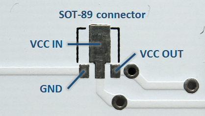 The connector is for voltage regulators in SOT-89 size packaging. Depending on the regulator and the wiring, it can be necessary to add additional capacitors. When using the connector on the back of the breakout board, remember to remove the 0 Ω bridging resistor on the front of the breakout board:
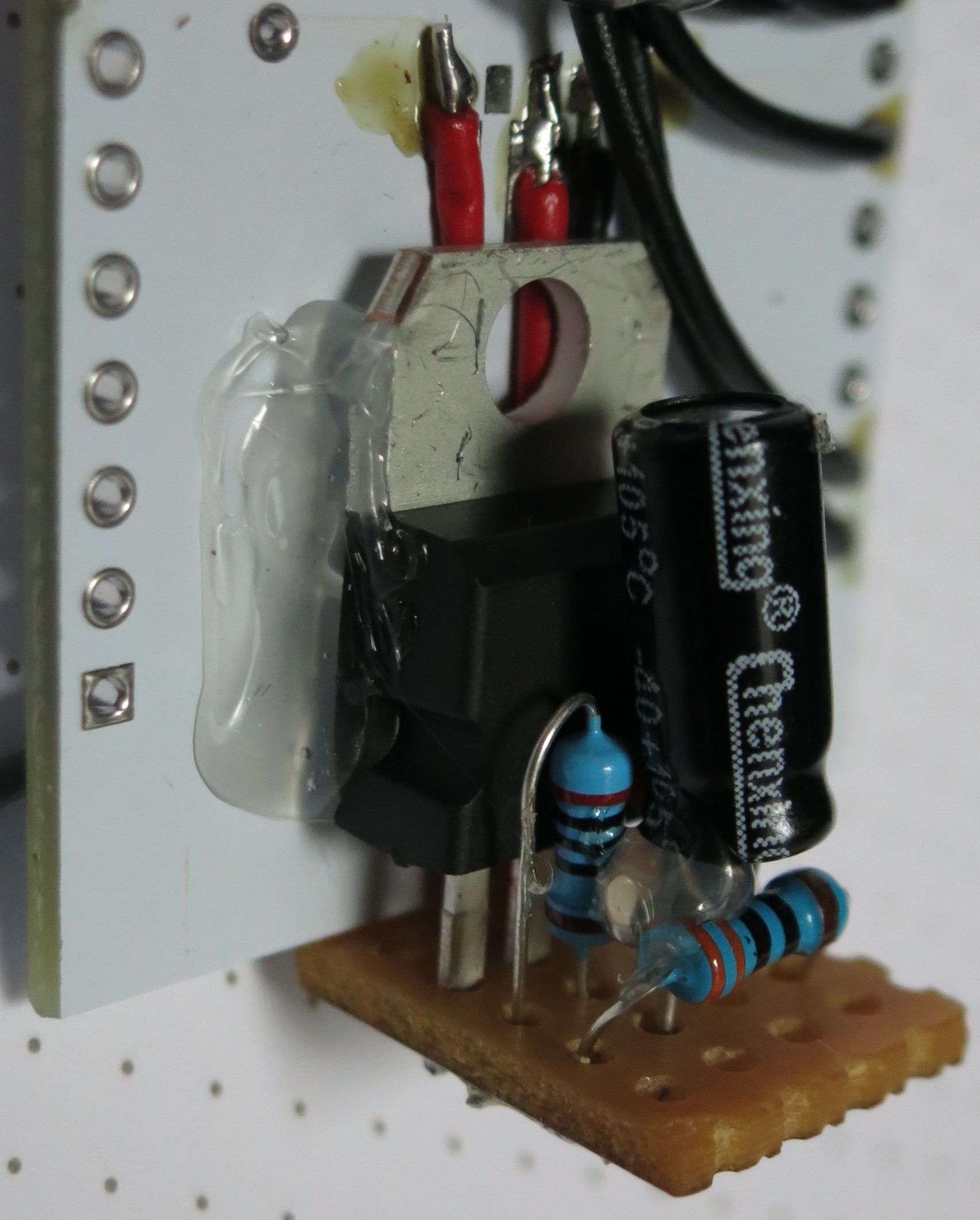
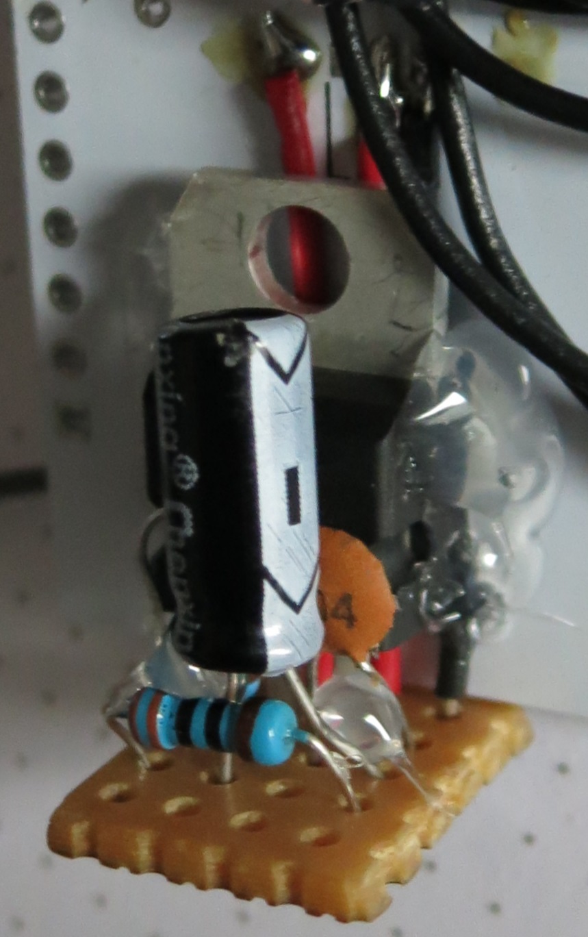
I had neither a 5 V to 3.3 V step down module nor a voltage regulator available, but a LM317 adjustable regulator, so I used that instead. I used the „standard“ circuit with 200 Ω for R1 and 330 Ω for R2 and two capacitors (0.1 μF and 1 μF):
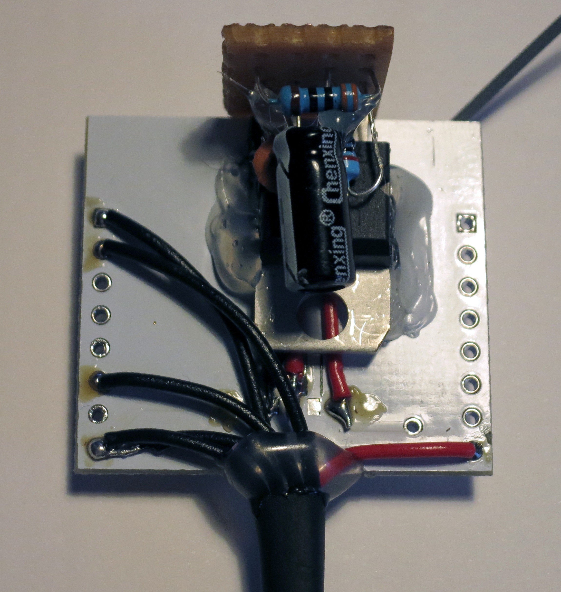
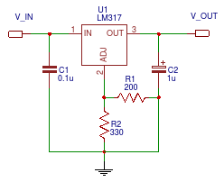 Sitting on a peace of stripboard and wired to the voltage regulator connector on the back of the breakout board, the result looks like this:
The Pixhawk’s telemetry ports have 6 pins. The Pixhawk from 3D Robotics has HIROSE DF13 connectors, whereas some other Pixhawks have Molex PicoBlade connectors. To connect the ESP telemetry module to the Pixhawk, a female 6-pin connector of the respective type with (at least) the following 4 wires is needed:
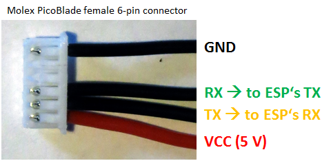 My Pixhawk came with a spare 6 wire cable, so I simply removed the two unnecessary wires (lift the clips which are holding the contacts in place), cut the cable in half and soldered it to the breakout board.
In addition to the Pixhawk connection, a normally open (NO) push-button should be connected to the ESP telemetry module’s GPIO2 and GND connectors to be able to reset the module (i.e. load the default settings).
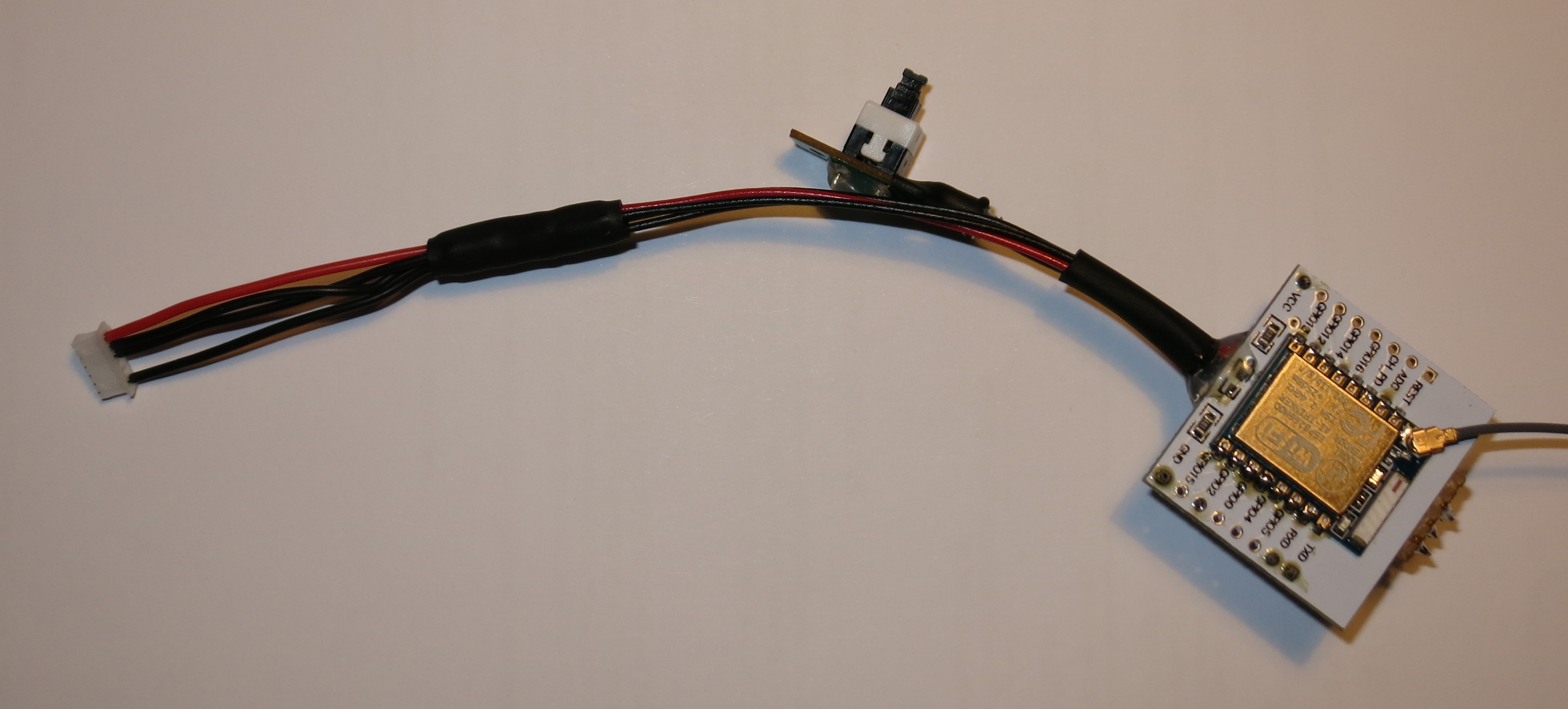
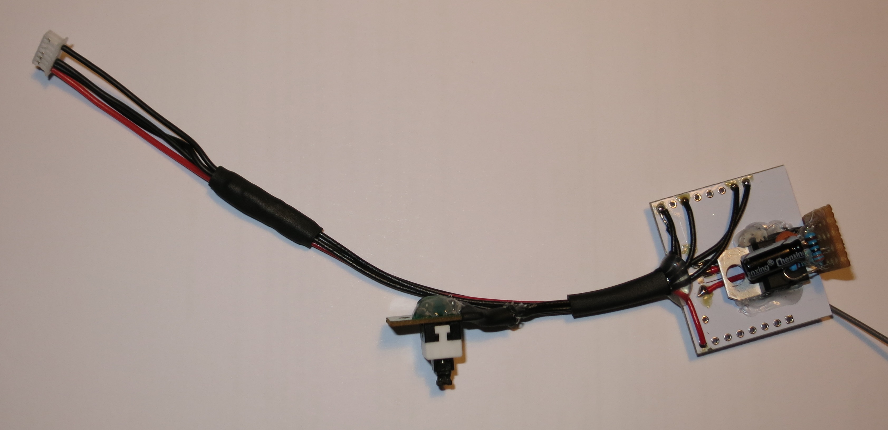
The result with heat-shrink tubing and hot glue applied looks like this:
Configuring the Pixhawk and connecting the ESP telemetry module
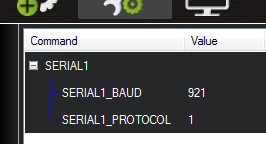
By default the MavESP8266 firmware is set to use a baud rate of 921600 for the serial connection to the Pixhawk, whereas the Pixhawk’s telemetry ports default to 57600 baud. To use the MavESP8266 firmware’s default (also being the maximum stable baud rate), the Pixhawk’s SERIAL1_BAUD config variable needs to be set to 921. Also check that SERIAL1_PROTOCOL is set to 1. (Use SERIAL2_BAUD and SERIAL2_PROTOCOL if using the TELEM2 port.)
The variables can be found in Mission Planner’s Full Parameter List or Full Parameter Tree when the Pixhawk is connected to Mission Planner:
Click Write Params after changing the values.
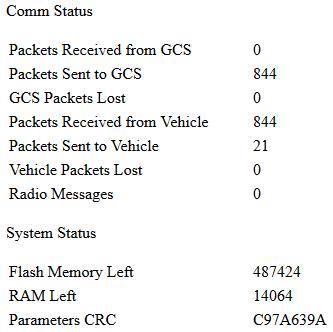
Now unpower the Pixhawk and connect the ESP telemetry module to the TELEM1 (or TELEM2) port. When re-powering the Pixhawk, the ESP telemetry module will act as an access point with the SSID „Pixracer“. To see if the setup is working as desired, connect to the „Pixracer“ Wi-Fi network (password „pixracer“) and point your browser to http://192.168.4.1/getstatus. The result should look like this, with Packets Received from Vehicle being greater than 0:
 You can also view and change parameters of the ESP telemetry module with HTTP GET requests, e.g. SSID, Wi-Fi channel and connecting to an existing Wi-Fi network. Unfortunately with MavESP8266 version 1.1.0 the output of http://192.168.4.1/getparameters is more or less unusable, showing integer values for all variables.
Connecting Mission Planner to the Pixhawk via Wi-Fi telemetry module
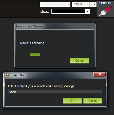
With your computer connected to the ESP telemetry module’s Wi-Fi network (default „Pixracer“), you can finally connect Mission Planner to the Pixhawk over Wi-Fi. In the top right corner choose UDP from the drop down menu (baud rate seems to be irrelevant) and click CONNECT. When asked for the Local port, enter 14550.
You should see the messages Connecting UDP, Waiting for UDP, Mavlink Connecting…, Done and finally a Getting Params 1 window.
If the connection does not work, try to disable your firewall. I use Windows 7’s default firewall and did not need to disable it.
Connecting QGroundControl to the Pixhawk via Wi-Fi telemetry module
QGroundControl will automatically detect the Pixhawk flight controller when connected to the ESP telemetry module’s Wi-Fi network. (Successfully tested on Windows 7 and Android Marshmallow).
As mentioned above: If the connection does not work, try to disable your firewall. I did not need to disable Windows 7’s default firewall. Android does not have a firewall by default.
Adding an external antenna to the ESP telemetry module
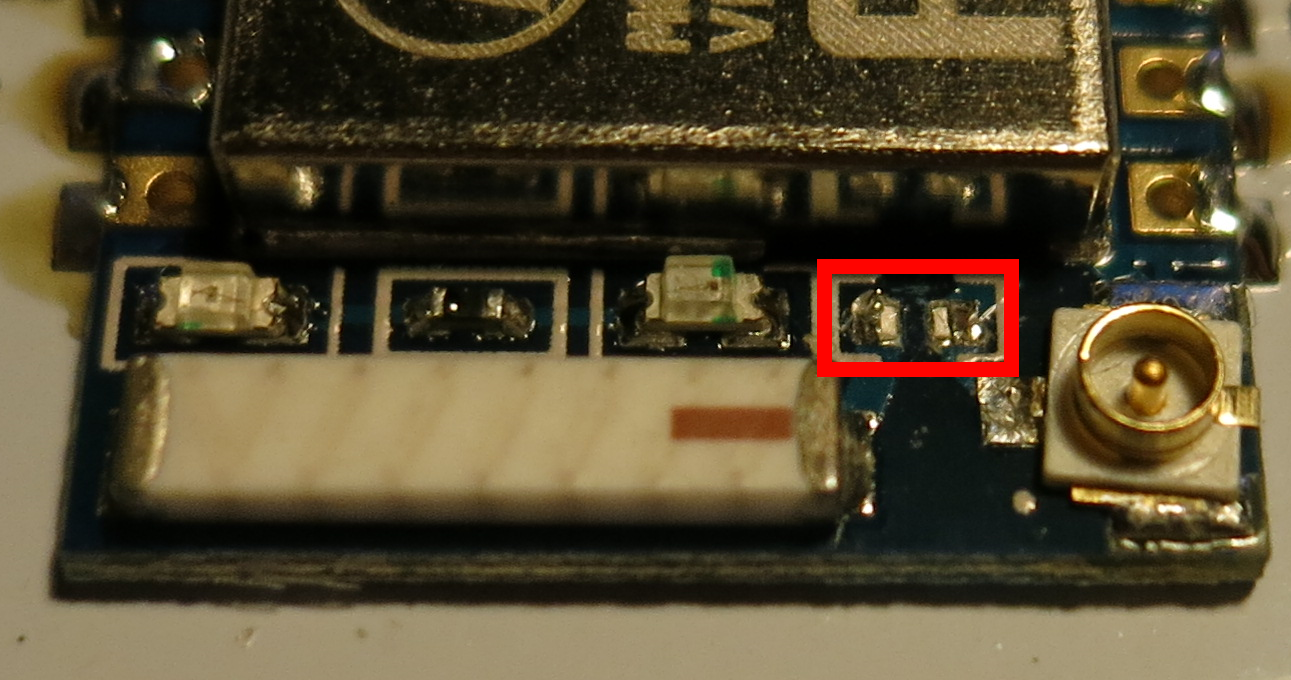
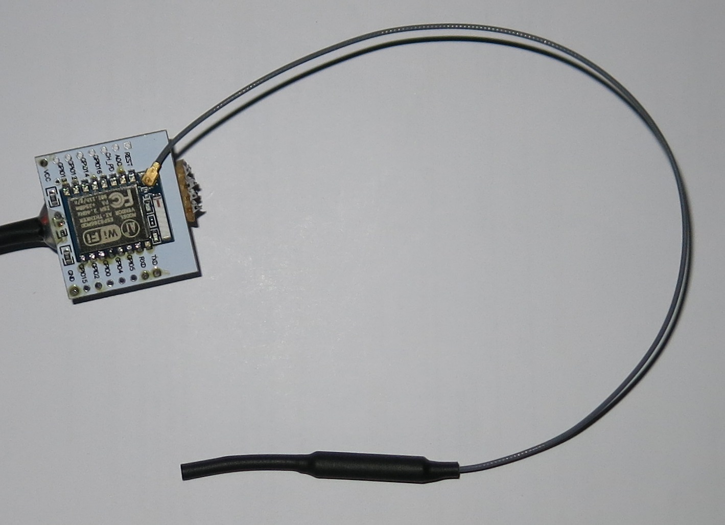
For better Wi-Fi performance when using the ESP telemetry module during flight it can be beneficial to connect an external antenna. The ESP-07 module has both, an on-board antenna and an U.FL connector for an external antenna. To use an external antenna, the on-board antenna needs to be disconnected by removing the 0 Ω bridging resistor:
After disconnecting the on-board antenna, the module should not be powered without attaching an external antenna!
The picture shows the ESP-07 module with attached 2.4 GHz antenna with an approximately 22 cm long antenna cable:
Conclusion
The MavESP8266 firmware can successfully be flashed to an ESP-07 module, which then turns into a bidirectional MAVLink Wi-Fi telemetry module with optional external antenna and can be connected to a Pixhawk flight controller.
Mission Planner can successfully connect to and communicate with the Pixhawk over Wi-Fi and UDP. QGroundControl automatically detects the Pixhawk when connected to the telemetry module’s Wi-Fi network.
The weight of the assembled ESP telemetry module with cables, antenna, voltage regulator and push-button is 14 gram.
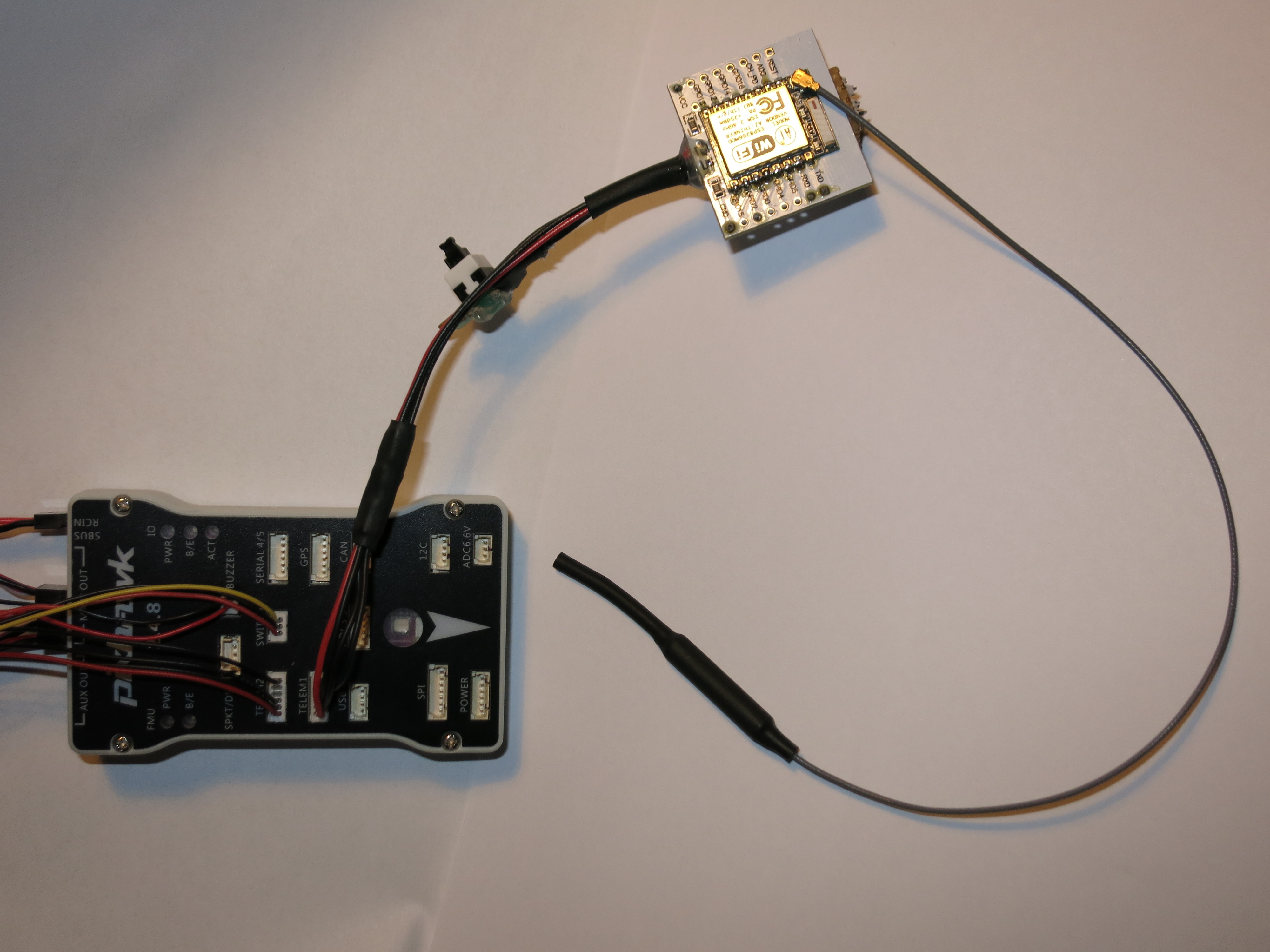
Let me know what you think! Last picture: the ESP-07 telemetry module connected to my Pixhawk:



Hi,
Very nice writeup very detailed and well layed out.
Actually I’ve also done same „setup“ using ESP-07 + external antenna.
I’m using the esp-link, https://github.com/jeelabs/esp-link.
Yet the range I’m getting in air and also in house is terrible, it’s good mainly for setup and parameters change but beside that I’m disappointing.
Wondering what are your findings regarding range.
Cheers, Eddi
Hi, thanks for the very clear and helpful writeup!
Have you ever tried to add the module to a different network and still connect to QGC?
I’ve been trying to change to STA mode and define an IP address, gateway etc to join my router’s network but I can’t then connect to the module from QGC or Mission Planner. Any help greatfully received!
Cheers,
Jono
Thanks for your shared, instructor step by step clearly,
So can you please help me connect one wifi cam to esp and transfer video to phone/laptop.
Reed Noel.
What APM boards? Will it work with APM 2.6? I am trying to make it work with APM 2.6 but I am unable to receive any heart beat from the vehicle. Is there any solution?
I used a PIXHAWK 2.4.8 from AliExpress. I think it should generally work with every board that supports MAVLink v1 at a serial port. You might find more information at the mavesp8266 repository: https://github.com/dogmaphobic/mavesp8266
mavesp8266 12ebin downloaded . device connected but no internet connection. please reply
Dear Ray
This is a very nice tutorial.
Could you help me please.
I got everything hooked up and working. I got the fw flashed, the connections ok. i’m using D1mini esp8266mod.
I configured sucessfully but cannot connect over wifi.
I can connect to the autopilot using the usb port of the ESP., but have no data over wifi. Nor on the website, there is 0 everywhere, neither on the mission planner.
Where go i to the wrong way?
Dear Gabor, I’m sorry, but I cannot give you any specific advice. Just summing up what I guess you already know: If you can connect to the autopilot using the ESP’s USB port, the connection between autopilot and mavesp8266 firmware seems to be working. (Didn’t even know it is posisble to use mavesp8266 firmware over USB/serial – is there a documentation for that?) If you can see the mavesp8266 website with the connection stats, the WiFi connection between your computer and the ESP also seems to be working. Next thing I would check is if anything is blocking UDP traffic from the ESP to your computer – e.g. a firewall on your computer?
Sorry, just re-read your comment. If there is 0 everywhere on the mavesp8266 firmware status website, then most probably the serial connection between the esp and the autopilot is not working. Double check the physical connection and the baud rate in the autopilot and the mavesp8266 settings.
Hii,
How to get data of pixhawk 2.4.8 using wifi telemetry
in azure cloud using wifi telemetry module please explain it
Kindly recheck the pinout given in the diagram „the designated connector on the back of these boards“